Valve Guides and Inserts

Valve guides are small holes machined into a cylinder head that allow the up-and-down movement of the intake and exhaust valves. A tight tolerance allows for lubrication of the valve stem and heat transfer into the cylinder head.
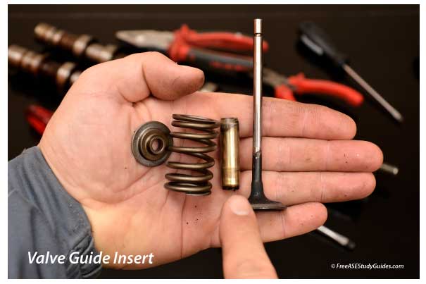
The valve guides in iron cylinder heads are machined directly into the head. Aluminum heads have valve guide inserts. The inserts are press-fit into slightly smaller holes. They use inserts because aluminum is not as strong as iron.
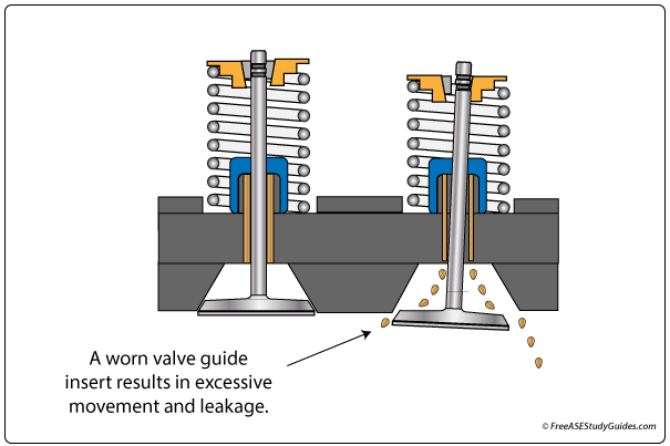
The clearance between the valve stem and guide can increase from wear. As a result, the valve stem moves more and more sideways in the guide leading to increased wear, oil consumption, and burned or bent valves.
After the head is removed and disassembled, side movement, valve stems, and guides are measured and compared to specifications.
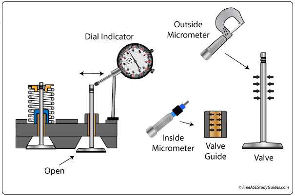
Some manufacturers recommend using a dial indicator to measure side-to-side movement, and others recommend measuring and subtracting the valve stem thickness from the valve guide inner diameter.